Product Description
Product Description
|
Material |
304/316/316L/CF3/CF8/CF8M/1.4301/1.4408/1.4404/SCH22/SCS13/SCS14/17-4PH/WCB/GS45/HK | ||
|
Standard |
DIN / JIS / ASTM / ASME / BS / GB / ISO |
||
| Thread Ending | NPT / BSPT / BSP / DIN / ISO | ||
| Product weight | 0.005kg~45kg | ||
| Dimensional tolerance | Casting ISO8062 CT5~CT7 ; Machining ISO2768 | ||
| Manufacturing process | Precision casting, investment casting, precision machining NC/CNC | ||
|
Application |
Stainless Steel Pipe System,water system, petrolum system etc.Medicine, food, chemical industry, etc |
||
| Type | Tee, elbow, union, pair wire, quick connector, clamp connector, valve, valve body, pump, impeller, mechanical parts, food machinery, stainless steel customized parts |
||
|
Service |
OEM |
||
|
Delivery |
By Sea / By Air / By Express |
||
| Shipping port | ZheJiang / QingDao / ZheJiang /BeiJin | ||
|
Packing |
Carton Box / Plywood Case / Special Packaging CHINAMFG Customer Requirements |
||
| Supply cycle | Samples are 25-35 days; the order can be adjusted according to the situation for 55 days of normal manufacturing period. | ||
|
Payment Terms |
100% TT / 30%TT in advance, balance 70% before delivery |
||
| Our advantage | We have more than 15 years of manufacturing management experience; we have professional technical engineers in investment casting, machining and quality inspection; we have long-term stable and continuous optimization of product quality and supply cycle management plHangZhou. |
||
Product Show
FAQ
1,What are your strengths?
We have foundry workshop and machining workshop; We have an independent quality inspection team and production process management team; We can provide you with the drawing mapping, mold or product design and manufacturing, as well as the inspection and monitoring management of your products in China;
2,When can I get the price?
The quotation shall provide detailed and complete information within 24 hours after receiving the inquiry. And solutions.
3,How long can you finish the sample?
It is usually completed in 3-5 weeks; Different products adjust the cycle.
4,How long can you finish the order?
After receiving the sample confirmation information, the casting time is usually 6-7 weeks; The finished product was added for another 2-3 weeks;
We welcome your inquiry and cooperation!
HangZhou CHINAMFG Electric Technology Co., Ltd

Can you explain the Concept of Slip in a Fluid Coupling?
In a fluid coupling, slip refers to the relative speed difference between the impeller and the runner. When the impeller, which is connected to the driving shaft, rotates, it induces the flow of hydraulic fluid inside the coupling. This fluid flow in turn drives the rotation of the runner, which is connected to the driven shaft.
However, due to the operating principle of fluid couplings, there is always a certain amount of slip between the impeller and the runner. This slip occurs because the fluid coupling needs to allow for a small speed difference in order to transmit torque smoothly.
During startup or under heavy load conditions, the impeller’s rotational speed may be slightly higher than the runner’s rotational speed. This speed difference causes the hydraulic fluid to circulate between the impeller and the runner, generating hydrodynamic forces that transmit torque from the driving shaft to the driven shaft.
Slip is an inherent and controlled characteristic of fluid couplings, and it is essential for their smooth operation. However, excessive slip can lead to energy losses and reduced efficiency. Therefore, fluid couplings are designed to have an optimal slip value for specific applications, balancing the need for torque transmission and energy efficiency.
Temperature Limitations of Fluid Couplings
Fluid couplings, like any mechanical component, have temperature limitations that must be considered to ensure their proper and safe operation. The temperature limitations of fluid couplings are influenced by the type of fluid used inside the coupling, the ambient operating conditions, and the specific design and construction of the coupling.
The primary concern regarding temperature is the heat generated during the operation of the fluid coupling. The heat is a result of friction and fluid shear within the coupling as it transmits power between the input and output shafts. Excessive heat generation can lead to the degradation of the fluid, affecting the performance and longevity of the coupling.
As a general guideline, most fluid couplings are designed to operate within a temperature range of -30°C to 80°C (-22°F to 176°F). However, the actual temperature limitations may vary depending on the manufacturer and the application requirements. For specific industrial applications where high-temperature environments are common, fluid couplings with higher temperature tolerances may be available.
It is crucial to consider the operating environment and the power demands of the machinery when selecting a fluid coupling. In applications with extreme temperatures, additional cooling mechanisms such as external cooling fins or cooling water circulation may be employed to maintain the fluid coupling within its safe operating temperature range.
Exceeding the recommended temperature limits can lead to premature wear, reduced efficiency, and even mechanical failure of the fluid coupling. Regular monitoring of the operating temperature and following the manufacturer’s guidelines for maintenance and fluid replacement can help ensure the longevity and reliability of the fluid coupling.
Always consult with the manufacturer or a qualified engineer to determine the specific temperature limitations and suitability of the fluid coupling for your particular application.
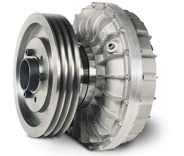
Principle of Hydrodynamic Fluid Coupling
A hydrodynamic fluid coupling operates on the principle of hydrokinetics, utilizing hydraulic fluid to transmit power between an engine or prime mover and a driven load. The key components of a fluid coupling are the impeller, the turbine, and the housing filled with hydraulic fluid.
Here’s how the principle works:
- Impeller: The impeller is connected to the engine’s crankshaft and is responsible for driving the hydraulic fluid. As the impeller rotates, it creates a flow of fluid within the housing.
- Fluid Flow: The rotational motion of the impeller causes the fluid to move radially outward, towards the housing walls. This generates a high-velocity fluid flow in the housing.
- Turbine: The turbine is connected to the driven load, such as a transmission or machinery input shaft. As the fluid flows onto the blades of the turbine, it causes the turbine to rotate.
- Power Transmission: The kinetic energy of the high-velocity fluid is transferred to the turbine, resulting in the rotation of the driven load. The power transmission is achieved purely through the hydrodynamic effect of the fluid flow.
- Slip: In a fluid coupling, there is always a slight difference in speed (slip) between the impeller and the turbine. This slip is necessary to allow the fluid to accelerate from rest to the speed of the turbine. As a result, the output speed of the driven load is always slightly less than the input speed from the engine.
Hydrodynamic fluid couplings provide several advantages, such as smooth power transmission, overload protection, and torsional vibration dampening. However, they do not provide torque multiplication like torque converters do, making them more suitable for applications where precise speed matching is required.


editor by CX 2023-11-21