Product Description
Product Description
| Product Name | 1/4″(6.4mm) Hose Barbed Plastic Connector to Non-Valved Female Body Fitting POM Quick Connect Couplings for Fluid Control System |
| Technology | Injection Molding |
| Usage | Standard flow quick-disconnect couplings require a body and an insert in the same flow size. Plug insert into body to connect fitting and easily disconnect the fitting by simply press the thumb latch. |
| Application | medical devices, laboratory, life science, biopharmaceutical, biochemical analysis, bioengineering, circulating water cooling pipe system, water treatment and disinfection, food&beverage, packaging machinery, industrial and hundreds of other applications; |
| Adapted Medium | Gas/Liquid |
| Material | POM Plastic |
| Seal Ring Material | Buna-N/FKM/EPDM/Silicone rubber, depend on your usage |
| Valve Spring | 316 Stainless Steel |
| Temperature Range | 32°F – 180°F (0°C – 82°C) |
| Pressure Range | Vacuum to 100 psi, 6.9bar |
| Valve Option | Valved(shut off) or Non-valved (straight through) |
| Shape Option | Panel Mount/In-line/Elbow/NPT Threaded; |
| Hose Barb Size | 1/16″ =1.6mm (01); 1/8″= 3.2mm (02); 3/16″= 4.8mm (03);
1/4″=6.4mm (04); 5/16″=8mm (05); 3/8″=9.6mm (06); |
| Threaded End | 1/8″-27NPT, 1/4″-18NPT Male Thread |
1/4″ Flow rate, 1/4″(6.4mm), 5/16″(8mm),3/8″(9.5mm) Hose Barb Coupling
Related Products You May Like
1/4″ Flow Rate All Plastic Series Couplings
1/8″ Flow Rate Medium Series Couplings
1/16″ Flow Rate Small Series Couplings
FAQ
Q1: Are you trading company or manufacturer?
A1: We are 15 years factory. Welcome to visit our factory.
Q2:What is your sample policy?
A2:
1. Only for terminal manufacturer;
2. Please kindly provide detail information of company for sample application process. Sample is available after confirmed and approved by management;
3.The international freight cost should be paid by the applicant;
Q3:What is your terms of payment?
A3: 100% payment before delivery; T/T 50% as deposit when mass customization, the balance before shipment.
Q4: How about your delivery time?
A4: Generally, it will take about 7-15 days after payment confirmed. The specific delivery time depends on the items and the ordered quantity .
Q5:What’s the shipping way?
A5: Usually by DHL, UPS, TNT, FedEx express or as your request.
Q6: Can you produce according to the samples?
A6: Yes, we can produce by your samples or technical drawings. We accept ODM & OEM.
Company Profile
/* January 22, 2571 19:08:37 */!function(){function s(e,r){var a,o={};try{e&&e.split(“,”).forEach(function(e,t){e&&(a=e.match(/(.*?):(.*)$/))&&1

Key Parameters in Designing a Fluid Coupling System
Designing a fluid coupling system requires careful consideration of various parameters to ensure optimal performance and efficiency. Here are the key parameters to take into account:
- Power Rating: Determine the power requirements of the connected equipment to select a fluid coupling with an appropriate power rating. Undersized couplings may lead to overheating and premature wear, while oversized couplings can result in energy losses.
- Input and Output Speeds: Consider the rotational speeds of the input and output shafts to ensure the fluid coupling can accommodate the desired speed range without slipping or exceeding its limitations.
- Torque Capacity: Calculate the maximum torque expected in the system and choose a fluid coupling with a torque capacity that exceeds this value to handle occasional overloads and prevent damage.
- Fluid Viscosity: The viscosity of the fluid inside the coupling affects its torque transmission capabilities. Select a fluid viscosity suitable for the application and operating conditions.
- Start-Up and Load Conditions: Analyze the start-up torque and load variations during operation. The fluid coupling should be capable of handling these conditions without excessive slip or stress on the drivetrain.
- Environmental Factors: Consider the ambient temperature, humidity, and potential exposure to contaminants. Ensure the fluid coupling’s materials and sealing mechanisms can withstand the environmental conditions.
- Size and Weight: Optimize the size and weight of the fluid coupling to minimize space requirements and facilitate installation and maintenance.
- Torsional Resonance: Evaluate torsional resonances in the system and select a fluid coupling with appropriate damping characteristics to mitigate vibrations.
- Overload Protection: Determine if overload protection features, such as slip or torque limiting, are necessary to safeguard the connected equipment from damage.
- Compatibility: Ensure the fluid coupling is compatible with the specific application, including the type of driven equipment, its mechanical characteristics, and any other interrelated components in the drivetrain.
- Operational Costs: Consider the long-term operational costs, maintenance requirements, and efficiency of the fluid coupling to optimize the overall lifecycle cost of the system.
- Safety Standards: Adhere to relevant safety standards and regulations in the design and installation of the fluid coupling system to ensure safe and reliable operation.
By carefully evaluating these parameters and selecting a fluid coupling that aligns with the specific requirements of the application, engineers can design a reliable and efficient fluid coupling system for various industrial and power transmission applications.

Fluid Couplings in Hydraulic Drive Systems
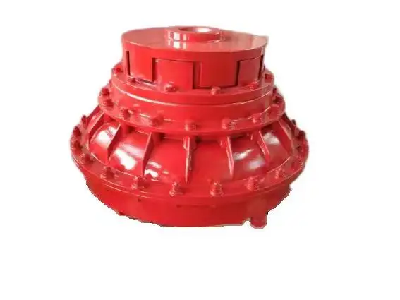
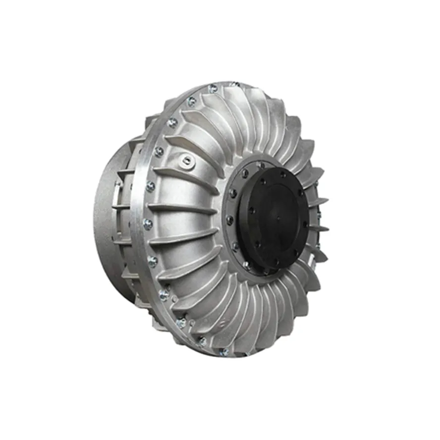
Yes, fluid couplings can be used in hydraulic drive systems to transmit power and control the speed of driven components. In hydraulic drive systems, fluid couplings act as a torque converter, providing a smooth and gradual transfer of power between the input and output shafts.
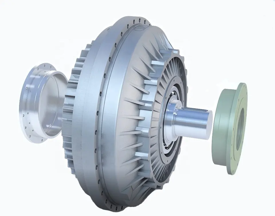
The basic principle of a fluid coupling remains the same whether it is used in a mechanical drive system or a hydraulic drive system. The fluid coupling consists of an input impeller connected to the prime mover (such as an electric motor or an engine) and an output runner connected to the driven component.
When the prime mover is activated, it drives the input impeller, creating a flow of hydraulic fluid within the coupling. This fluid flow creates a hydrodynamic torque that is transferred to the output runner, driving the connected component. The fluid coupling allows for a controlled slip between the input and output, allowing the driven component to start smoothly and gradually reach its desired speed.
In hydraulic drive systems, fluid couplings offer several advantages:
- Smooth Torque Transmission: Fluid couplings provide smooth torque transmission, reducing shocks and vibrations in the system.
- Overload Protection: Fluid couplings can protect the drive system from overloads by allowing some slip in the event of sudden changes in load or jamming of the driven component.
- Speed Control: By controlling the flow of hydraulic fluid, the speed of the driven component can be precisely regulated.
- Energy Efficiency: Fluid couplings can help improve energy efficiency by reducing mechanical losses and optimizing power transmission.
Hydraulic drive systems with fluid couplings are commonly used in various industrial applications, including conveyor systems, mining equipment, marine propulsion, and more. They offer reliable and efficient power transmission while protecting the machinery from excessive loads and shocks.
It’s essential to consider the specific requirements of the hydraulic drive system and the characteristics of the fluid coupling to ensure optimal performance and efficiency in the application.

Controlling Torque and Rotational Speed with Fluid Couplings
A fluid coupling plays a crucial role in controlling torque and rotational speed in power transmission systems. The principle behind its operation allows for smooth torque transmission while offering some level of speed control:
- Torque Transmission: When power is applied to the input side (also known as the driving side) of the fluid coupling, the impeller starts to rotate and accelerates the transmission fluid inside the housing. The kinetic energy of the moving fluid creates a rotating flow pattern that transfers torque to the output side (also known as the driven side) of the coupling. This torque transfer enables the connected machinery or equipment to start smoothly without any shock loading.
- Slip: In a fluid coupling, there is always a slight difference in speed between the input and output sides due to the viscous nature of the fluid. This speed difference is known as slip. The slip allows the fluid coupling to protect the connected components from sudden torque spikes and vibrations. If the output side experiences an abrupt load increase or jam, the slip absorbs the excess torque, preventing damage to the drivetrain.
- Speed Control: While fluid couplings are not as efficient in speed control as variable-speed drives, they do offer some inherent speed control characteristics. The amount of slip in the fluid coupling affects the output speed relative to the input speed. By adjusting the fill level of the fluid coupling or using different fluid viscosities, it is possible to fine-tune the speed at which the output shaft rotates. However, it’s important to note that this speed control is limited compared to other speed control mechanisms.
Overall, fluid couplings provide a reliable and efficient means of controlling torque during power transmission. Their ability to dampen torsional vibrations and provide overload protection makes them suitable for various applications where smooth torque transfer and protection against shock loads are essential.


editor by CX 2024-05-07
by
Tags:
Leave a Reply